
The Rogowski coil, introduced in 1912 by W. Rogowski and W. Steinhaus, is a coreless, flexible, non-saturating, air-wound coil used for measuring AC currents; such as high-speed transients; pulsed currents or power frequency sinusoidal current.
Despite its conceptual promise, the Rogowski coil remained largely theoretical for decades. Practical adoption only began in the latter half of the 20th century with the advent of modern electronics. Key advancements in integrated circuits such as operational amplifiers (op amps) enabled the precise integration and processing of signals from Rogowski coils, this coupled with PEM’s pioneering work on stabilising the low frequency drift and wide-band integration, made them practical for industrial and research applications.
Today, Rogowski coils are widely used in power electronics for applications such as current measurement in converters, motor drives, grid monitoring, and fault analysis.
How Rogowski Coil Works
In its simplest form a Rogowski coil is an evenly wound coil of N turns per metre on a non-magnetic former of constant cross sectional area A. The winding wire is returned to the starting point along the central axis of the former and the two ends are typically connected to a cable. The free end of the coil is normally inserted into a socket adjacent to the cable connection in a way that allows it to be unplugged thus enabling the coil to be looped around the conductor carrying the current to be measured.
An alternating or pulsed current in a conductor develops a magnetic field and the interaction of this magnetic field and the Rogowski coil local to the field gives rise to an induced voltage within the coil which is proportional to the rate of change of the current being measured. Provided the coil constitutes a closed loop with no discontinuities, it may be shown that the voltage E induced in the coil is proportional to the rate of change of the encircled current I according to the relationship E=H.dI/dt, where H, the coil sensitivity in (Vs/A), is proportional to NA.
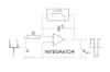
To obtain an output voltage Vout proportional to I it is necessary to integrate the coil voltage E; hence an electronic integrator is used to provide a bandwidth extending down to below 1Hz.
The op-amp integrator, in its simplest form, with an input resistor Rsh and feedback capacitor C has an output Vout=(1/CR)∫ Edt. The overall probe gain is therefore given by, Vout=RshI, where Rsh= H/CR is the probe sensitivity (V/A).
The relationship Vout proportional to I is valid throughout the probe bandwidth. The bandwidth is defined as the range of frequencies from fL to fH for which sinusoidal currents can be measured to within 3dB of the specified sensitivity Rsh.
At low frequencies the integrator gain increases and in theory will become infinite as the frequency approaches zero. This would result in unacceptable dc drift and low frequency noise; hence the integrator gain has to be limited at low frequencies. This limitation is achieved by placing a low pass filter in parallel with the integrating capacitor. The low pass filter sets the low frequency bandwidth fL, typically this is less than 1Hz.
Furthermore, due to the distributed inductance and capacitance of the Rogowski coil there is a high frequency bandwidth fH, (generally 1MHz or greater) above which the measurement is attenuated and significant phase delay occurs. The bandwidth of the electronic integrator and the length of cable connecting the integrator to the coil also influence this limit.
PEM has developed mathematical models of the Rogowski coil
Over many years, PEM has developed mathematical models of the Rogowski coil, cable and integrator allowing us to develop reliable, accurate current probes in a variety of sizes for an ever growing market.
Using a Rogowski coil to measure AC or fast transient currents has many advantages over other methods of current measurement:
- Simple to retro-fit, the clip-around Rogowski coil sensor is thin, lightweight, flexible and robust
- Coil size is not dependant on the magnitude of the current to be measured
- Coils small enough to fit between the legs of a TO-220 semi-conductor
- 20m coils to fit round a wind-turbine.
- Non-Intrusive (presents the equivalent of only a few pH to the circuit under test)
- Wide-bandwidth devices with predictable frequency response, ideal for power quality measurement or monitoring complex waveforms.
- Intrinsically safe - No danger of an open circuit secondary.
- Galvanic isolation
- Excellent linearity (Rogowski coils have no magnetic materials to saturate)
- Capable of taking huge overload currents without damage
- Immune to DC Currents - as a result it can measure small AC currents in the presence of a large DC component